Ball Grid Array Example for the
Surface Evolver
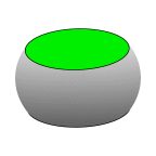
 A ball grid array (BGA) joint is a bead of solder between two circular
pads. Arrays of these joints are used to mount chips on circuit boards.
This set of examples models one such joint, beginning very simply and
adding features until a fairly complex model is reached. A list of the
various datafiles is below, with brief descriptions. Each datafile has
its own page, which elaborates on the added features and their implementation.
Note that the ordering of the datafiles is tree-like, rather than linear.
The complete set of datafiles and auxiliary command files is available in
bga-files.zip
or bga-files.tar.
NOTE: These models require
Evolver version 2.12 (March 21, 1999)
or higher to run.
One of the benefits of writing my own software is that if it needs
features, I can add them. Some of the datafiles could run on old
versions with a little editing, but some definitely need the new
features.
It is assumed that you are familiar with the operation of the Surface
Evolver at least to the level of the basic
Evolver Tutorial examples
cube.fe,
cat.fe, and
mound.fe.
The general sequence of steps in modeling a surface is:
- Create a physical/mathematical model, in the sense of
deciding on geometry, energies, and constraints.
- Construct an initial datafile embodying the model, with appropriate
variables, constraints, quantities, and geometric elements.
- Figure out a good evolution script.
- Write scripts for the calculation of whatever forces, torques, etc.
you want as output data.
- Estimate the accuracy of your data as a function of refinement,
using known special cases or by looking at the convergence of a
sequence of values for successive refinements.
- Write scripts to automatically evolve and collect data over a range
of parameters.
The Datafiles:
The sequence of datafiles starts simple and adds features. The sequence
is not strictly linear; the main sequence keeps the contact surface on
the chip explicitly represented by facets, and a sideline replaces those
facets with edge integrals. Each datafile link here opens a commentary
page, from which one can also open the datafile in a separate browser
window. The idea is to be able to look at the commentary and datafile
simultaneously. The datafiles themselves also contain a little commentary.
You are also urged to have the Evolver running and run the models
as they are discussed.
-
bga-1.fe
Simplest model. Start here.
Fixed, concentric pads, with the solder
fully enclosed by facets.
-
bga-2.fe
Bga-2.fe with no_refine top and bottom.
-
bga-3.fe
Bga-2.fe with realistic surface tension and gravity.
-
bga-4.fe
Bga-3.fe, with various ways to calculate the vertical force on the
upper pad.
-
bga-5.fe
Bga-3.fe with vertical load and optimizing pad height.
-
bga-6.fe
Bga-5.fe with upper and lower barriers
-
bga-7.fe
Bga-3.fe with lateral movement of upper pad.
-
bga-8.fe
Bga-7.fe converted to boundary on top in anticipation
of optimizing lateral position and tilting.
-
bga-9.fe
Bga-8.fe with z and offset as optimizing parameters.
And vertical and horizontal loads.
-
bga-10.fe
Bga-8.fe with 3D motion and tilting one way.
With forces and torque.
-
bga-11.fe
Bga-10.fe with optimizing parameters.
-
bga-12.fe
Bga-11.fe with boundary integrals to replace top and bottom
-
bga-30.fe
String model equivalent of bga-1.fe, taking advantage of circular symmetry.
-
bga-31.fe
Like bga-30.fe, but with specified contact angle on pads.
Surface Evolver home page
More Surface Evolver examples
Ken Brakke's home page
 A ball grid array (BGA) joint is a bead of solder between two circular
pads. Arrays of these joints are used to mount chips on circuit boards.
This set of examples models one such joint, beginning very simply and
adding features until a fairly complex model is reached. A list of the
various datafiles is below, with brief descriptions. Each datafile has
its own page, which elaborates on the added features and their implementation.
Note that the ordering of the datafiles is tree-like, rather than linear.
The complete set of datafiles and auxiliary command files is available in
bga-files.zip
or bga-files.tar.